
In the pursuit of high-efficiency power conversion, Silicon Carbide Metal-Oxide-Semiconductor Field-Effect Transistors (SiC MOSFETs) are reshaping the power electronics landscape with their superior performance. Among their critical characteristics, the on-resistance (Rdson) directly impacts device efficiency and reliability.
As the next generation of power semiconductor devices, SiC MOSFETs are gradually replacing conventional silicon-based components in applications such as electric vehicles, photovoltaic inverters, and industrial power supplies, thanks to their high breakdown voltage, fast switching capability, and high-temperature operation.
On-resistance (Rdson), one of the most essential parameters of SiC MOSFETs, has a direct influence on conduction losses, operating efficiency, and thermal performance. Accurate and reliable Rdson measurement is therefore crucial for device selection, characterization, and application optimization.
1. What is Rdson, and why does it exist?
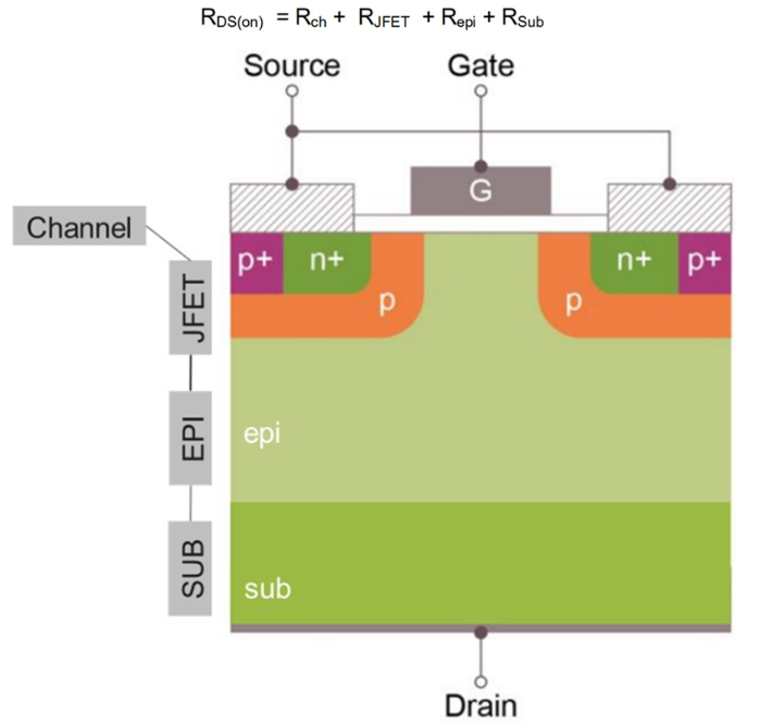
Rdson (on-resistance) refers to the total resistance between the drain and source when a SiC MOSFET is in the fully ON state. It is primarily composed of:
● Channel resistance (Rch)
● JFET resistance (RJFET)
● Epitaxial drift region resistance (Repi)
● Substrate resistance (Rsub)
In an ideal switching device, the on-resistance would be zero. In practice, however, due to material properties and physical structure, there is always a finite resistance, Rdson. This resistance results in conduction losses (I²×R), reduces system efficiency, and causes to device heating.
2. Factors Affecting Rdson
2.1 Material Properties
Although SiC offers superior intrinsic properties compared with silicon, the SiC–SiO₂ interface exhibits a much higher density of defects than its silicon counterpart. These interface traps reduce the inversion channel mobility, thereby increasing the channel resistance.
2.2 Temperature Dependence
The Rdson of SiC MOSFETs shows a positive temperature coefficient, meaning it increases as temperature rises. For example, Infineon’s IMZC120R034M2H exhibits an Rdson of 80 mΩ at 175 °C, which is approximately 2.3 times higher than its 34 mΩ value at room temperature.
2.3 Device Design and Structure
SiC MOSFETs typically use short-channel designs to minimize channel resistance. The share of channel resistance in the overall Rdson strongly influences its temperature behavior:
● Trench-gate devices (e.g., Infineon CoolSiC™): lower channel resistance share, more pronounced positive temperature coefficient.
● Planar-gate devices: higher channel resistance share, where the negative temperature coefficient of channel resistance partly offsets the positive coefficients of other resistance components, leading to a flatter overall Rdson temperature dependence.
2.4 Gate Drive Voltage
Gate voltage has a significant effect on Rdson. Using the same Infineon IMZC120R034M2H device as an example: with an 18 V gate drive, Rdson is 34 mΩ (fully ON). When the gate drive is reduced to 15 V, Rdson increases to 42 mΩ.
2.5 Threshold Voltage Drift (Long-Term Stability)
The gate oxide and SiC–SiO₂ interface traps can capture electrons, causing the threshold voltage (Vth) to shift upward over time. Because channel resistance is correlated with Vth, this results in an Rdson increase with device aging. Optimized gate oxide engineering can mitigate threshold voltage drift and improve long-term stability.
3. Rdson Measurement Methods
3.1 Conventional DC Method
The most straightforward approach is to measure the drain–source voltage (VDS) under conduction while simultaneously measuring the drain current (ID), and then calculate Rdson using Ohm’s law: Rdson = Vds / Id
Key considerations during measurement include:
● Applying sufficient gate voltage to ensure the device is fully turned on.
● Using a four-wire Kelvin connection to eliminate lead resistance errors.
● Maintaining stable junction temperature, since Rdson is highly temperature-sensitive.
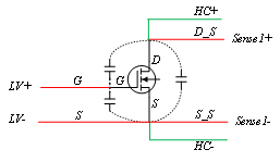
Figure 1 Schematic Diagram of the DC Rdson Measurement Method
3.2 Dynamic Measurement Method
For certain applications (e.g., low-side MOSFETs in switch-mode power supplies), Rdson must be evaluated during switching pulses. This requires synchronized measurement of the inductor current and the voltage drop across the low-side MOSFET, placing stringent demands on the test equipment in terms of bandwidth and synchronization.
3.3 Online Monitoring with Dedicated Gate Driver ICs
Modern gate driver ICs provide real-time monitoring of the conduction voltage (VDSON) through DESAT pins. By combining this voltage data with phase current information, Rdson can be calculated.
This method improves accuracy by subtracting two DESAT voltage samples, effectively canceling out unknown parasitic voltage drops in the application circuit (e.g., diode forward voltage VF).
4. Key Considerations and Common Issues in Rdson Measurement
4.1 Temperature Control and Measurement
Since Rdson is highly temperature-dependent, precise control and monitoring of junction temperature are essential. Typical challenges include:
● Self-heating from test current:
The current used for measurement can cause significant device heating if not properly managed. This requires a current source with fast output response and high sampling speed.
For example, the PLANCK 3200 High-Current Source Measure Unit provides up to 2000 A output capability, with a current rise time of <20 μs and a voltage sampling rate of 5 MS/s. This minimizes self-heating effects during Rdson testing.
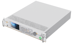
Figure 2 PLANCK 3200 SMU
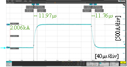
Figure 3 Waveform: 2000 A output, ~12 μs current rise time with PLANCK 3200 SMU
● Ambient temperature fluctuations:
Environmental variations can affect measurement repeatability and must be minimized or compensated.
4.2 Sources of Measurement Error
Measurement errors can be classified into three categories:
● Systematic errors: DC offset, gain error, hardware design limitations.
● Quantization errors: Resolution limits of the instrument’s ADC.
● Random errors: Thermal noise or other stochastic noise sources in the measurement system.
4.3 Test Condition Selection
The choice of gate drive voltage (Vgs) strongly influences the measured Rdson. Test conditions should reflect the intended application environment, and the applied Vgs must always be clearly documented in the test report.
4.4 Equipment and Connection Effects
Systematic deviations may arise from differences between test setups or instruments. Using four-wire Kelvin measurement and low-thermal EMF leads reduces these errors.
The PLANCK 3200 SMU features dual remote-sense channels, enabling two DUTs to be tested simultaneously under true four-wire measurement conditions. This eliminates wiring-related errors and significantly improves test efficiency.
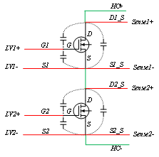
Figure 4 dual DUT four-wire
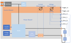
Figure 5 PLANCK four-wire dual-channel test schematic
4.5 Long-Term Stability Testing
For applications with high reliability requirements, long-term Rdson drift due to threshold voltage shift must be evaluated. Gate-switching stress tests can be employed to simulate real switching conditions and assess parameter stability over time.
5. Conclusion
Rdson testing of SiC MOSFETs is a complex process involving device physics, measurement methodology, temperature effects, and long-term stability considerations.
Selecting the appropriate test method, carefully controlling test conditions, and understanding the physical principles behind the data are critical for accurately evaluating SiC MOSFET performance.
Thank you for choosing Planck. If you have any business cooperation needs, please feel free to leave a message online. We will properly protect and legally use the information you provide, and arrange for business personnel to contact you as soon as possible!
Thank you for choosing Planck. If you have any business cooperation needs, please feel free to leave a message online. We will properly protect and legally use the information you provide, and arrange for business personnel to contact you as soon as possible!